

Post by bob0627 on Nov 25, 2013 8:22:02 GMT -5
NOTE: Without the work of such organizations as AE911, the following could have never been exposed. It takes the collective work of over 2,000 experts to be able to expose the critical details of NIST's blatant fraud and to understand its significance.
In the October Blueprint, AE911Truth published the conclusion of Chris Sarns’ five-part series in which he documented five key misstatements in NIST’s explanation of the initiation of collapse of WTC 7. August had previously seen the introduction of four short videos produced by a small team of international, independent researchers who are working in collaboration with AE911Truth. These analyses can be understood by anyone willing to study the details.
We expand here on the last of the four videos, entitled ‘MaladmiNISTration,’ as it introduced new information following NIST’s June 2012 Erratum document in which they admitted errors in their report.
Our short video from last month’s article on the subject will help to reacquaint you with this important development:
Our research into the initiation event of WTC7’s collapse began with a study of NCSTAR 1-9, where NIST asserted on page 527 (PDF page 593) that the failed girder seat on column 79 on floor 13 was 11” wide. However, we noted that on “Frankel” shop drawing #1091, this seat was 12” wide. This seemingly innocuous discrepancy led us to dig deeper.
We read of NIST’s contention that heat had caused five 13th floor beams, framing into a long span girder, to expand. They said that 5.5” was enough to push the girder across its 11” seat on column 79 beyond the vertical web, so that the lower flange of the girder became exposed to the entire weight of that floor area. NIST said that the flange could not support that load and folded upwards.
We further noted that NIST said that the 5.5” expansion was the maximum possible expansion. This is because any additional heating would soften the beam, leading to sagging rather than any greater pushing.
Thus NIST’s claim of an 11” beam seat and the maximum push of 5.5” were inextricably interwoven. Both had to be true for NIST's explanation to work. When NIST was notified last year about the seat width discrepancy, they issued an erratum document admitting this error in June 2012.
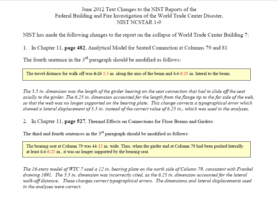
Figure 1. June 2012 Erratum. Source: www.nist.gov/customcf/get_pdf.cfm?pub_id=901225
However, in that same document they went on to say that they had also spotted another error, and added another paragraph to their erratum document. They claimed that a ‘typographical error’ had been made and that the 5.5” distance should have been 6.25. Apparently they had transposed two figures, said to be axial and lateral expansion figures, and this new erratum document simply reversed them.
With the beam seat confirmed at 12” wide and the newly required sideways movement 6.25”, they nevertheless stood by their original theory.
We suspect that the original error was caused by NIST carelessly confusing column 81 with column 79. Seen below is their admission that they commingled C81 and C79 modeling data.
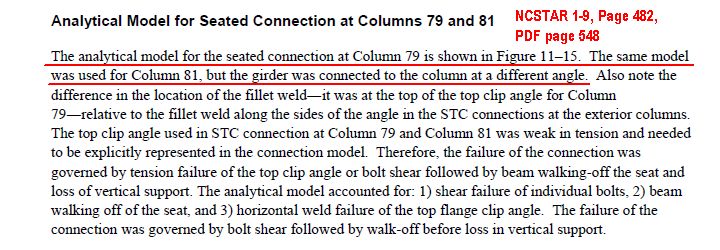
Figure 2. Column 79 and 81 modeled the same. Source: www.nist.gov/manuscript-publication-search.cfm?pub_id=861611
We discovered that the girder seat on column 81 was 11” wide, according to Frankel shop drawing 1083.
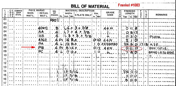
Figure 3. Frankel 1083 Bill of Material. Source: www2.ae911truth.org/downloads/NIST_WTC7_FOIA_11-209.zip
Now that the newly required sideways shift distance of 6.25” was confirmed for the acknowledged 12”wide girder seat, then NIST’s earlier contention concerning the maximum heat (600° C.) before the beams would sag, would come into question.
In our earlier videos we presented our carefully calculated findings that at the temperature required to expand by 6.25”, the beam would indeed have lost much of its strength, and would certainly be sagging rather than pushing the girder.
Yet another careless error by NIST was found. While discussing how we should raise this subject with NIST, a member of our team made another startling discovery which moved the entire debate into new territory. Upon close examination of the connection between Column 79 and the girder – a connection that NIST claimed failed – he spotted another steel element in the drawing that had not been previously mentioned. “Stiffener plates” were specified at the end of the girder and welded in place to both sides of the web and to the bottom flange.
NIST’s failure to show these stiffeners or take them into account in its analysis is yet another area where the omissions and incorrect statements are so egregious, anyone who understands these issues must by now begin to question NIST’s motives.
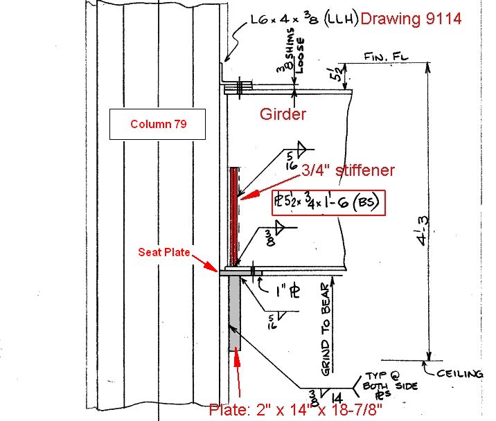
Figure 4. Frankel Drawing 9114, Elevation Detail, with stiffeners highlighted. Source: www2.ae911truth.org/downloads/NIST_WTC7_FOIA_12-009.zip
When we mentioned these stiffeners to mechanical engineer Tony Szamboti, who is involved in structural design in his professional work, he explained their role in such situations. He went on to say “The discovery of the girder stiffeners plates in drawing #9114 is a game changer, because this drawing covers the exact location where NIST says the collapse initiated.”
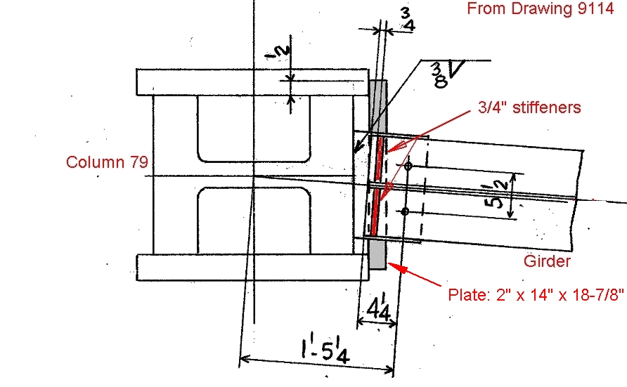
Figure 5. C79 shown on Frankel 9114 – Plan Detail. Source: imageshack.com/scaled/large/707/54ol.jpg
Basically, they brace the end of a girder between the lower load bearing flange and its vertical web so that if for any reason the girder did move laterally on its seat then the flange can transmit the extra load to that web and not fold upwards. In effect they make an I-beam end almost into a 'box' section.
This discovery changes the debate. Whether the girder travel was 5.5” or 6.25” was now irrelevant because even at up to a 9” move laterally that girder end would now have sufficient strength to remain on its seat. (It should be remembered that the girder was also held in place vertically by the five attached beams that were framed into it, and therefore the girder could not ‘tip’ over sideways either – as was also postulated by NIST.)
Figure 6. WTC 7 before 9/11. Source: 3.bp.blogspot.com/_itpY6Fvp9dM/SiTHGz9RTBI/AAAAAAAAACU/V8MOkbuB9UU/s320/wtc7.jpg
The presence of these stiffener plates was brought to NIST’s attention by structural engineers. The lack of response from NIST has been deafening, until just a few weeks ago.
On October 25, 2013, NIST replied to questions about the failure to include the stiffeners in many figures in the final WTC 7 report. They did acknowledge that they had consulted Frankel shop drawing #9114, but claimed:
“The web stiffeners shown at the end of the girder in Frankel drawing #9114 prevent web crippling. The structural analyses of WTC 7 did not show any web crippling failures. Therefore, the web crippling plates did not need to be included in the models/analyses.”
The entire thread can be viewed at 911blogger.com/news/2013-11-06/nist-replies-stiffeners-inquiry.
How can this new information be used to help in the push for an independent investigation of the total free-fall destruction of World Trade Center 7? If NIST’s theory regarding the initiation of the collapse of WTC 7 has now been shown to be faulty, then surely they should revisit and correct their theory, including their entire computerized model (since it contains initiating events that cannot be the correct ones).
When a small team of citizen activists can discover major discrepancies and careless errors throughout what should have been the most critical and carefully reviewed part of the entire report, then what confidence should anyone have in the rest of that report, or their other reports about what happened on 9/11? Indeed Architects and Engineers for 911 Truth has documented dozens of other examples of fraud in the NIST reports in our landmark DVD 9/11: Explosive Evidence – Experts Speak Out.
Please Help Us Carry This Vital Work Forward
We invite qualified individuals worldwide to join us as we continue to expose incorrect statements by NIST in the effort to trigger the initiation of a genuine investigation of the total, near-free-fall destruction of all three WTC towers on 9/11. Anyone who can read blueprints, edit audio or video, make and/or analyze engineering calculations, or write and edit, is encouraged to volunteer to help us at nineeleven247@yahoo.com.
In addition, AE911Truth is seeking funding for various legal actions connected to the NIST reports, such as lawsuits under the Freedom of Information Act (FOIA), claims against the validity of the NIST Reports, and the like. To make a donation to support this vital area of our work, please visit the AE911Truth Donations page, or call the office at 510-292-4710 and leave a message.
www.ae911truth.org/en/news-section/41-articles/822-maladministration.html
In the October Blueprint, AE911Truth published the conclusion of Chris Sarns’ five-part series in which he documented five key misstatements in NIST’s explanation of the initiation of collapse of WTC 7. August had previously seen the introduction of four short videos produced by a small team of international, independent researchers who are working in collaboration with AE911Truth. These analyses can be understood by anyone willing to study the details.
We expand here on the last of the four videos, entitled ‘MaladmiNISTration,’ as it introduced new information following NIST’s June 2012 Erratum document in which they admitted errors in their report.
Our short video from last month’s article on the subject will help to reacquaint you with this important development:
Our research into the initiation event of WTC7’s collapse began with a study of NCSTAR 1-9, where NIST asserted on page 527 (PDF page 593) that the failed girder seat on column 79 on floor 13 was 11” wide. However, we noted that on “Frankel” shop drawing #1091, this seat was 12” wide. This seemingly innocuous discrepancy led us to dig deeper.
We read of NIST’s contention that heat had caused five 13th floor beams, framing into a long span girder, to expand. They said that 5.5” was enough to push the girder across its 11” seat on column 79 beyond the vertical web, so that the lower flange of the girder became exposed to the entire weight of that floor area. NIST said that the flange could not support that load and folded upwards.
We further noted that NIST said that the 5.5” expansion was the maximum possible expansion. This is because any additional heating would soften the beam, leading to sagging rather than any greater pushing.
Thus NIST’s claim of an 11” beam seat and the maximum push of 5.5” were inextricably interwoven. Both had to be true for NIST's explanation to work. When NIST was notified last year about the seat width discrepancy, they issued an erratum document admitting this error in June 2012.
Figure 1. June 2012 Erratum. Source: www.nist.gov/customcf/get_pdf.cfm?pub_id=901225
However, in that same document they went on to say that they had also spotted another error, and added another paragraph to their erratum document. They claimed that a ‘typographical error’ had been made and that the 5.5” distance should have been 6.25. Apparently they had transposed two figures, said to be axial and lateral expansion figures, and this new erratum document simply reversed them.
With the beam seat confirmed at 12” wide and the newly required sideways movement 6.25”, they nevertheless stood by their original theory.
We suspect that the original error was caused by NIST carelessly confusing column 81 with column 79. Seen below is their admission that they commingled C81 and C79 modeling data.
Figure 2. Column 79 and 81 modeled the same. Source: www.nist.gov/manuscript-publication-search.cfm?pub_id=861611
We discovered that the girder seat on column 81 was 11” wide, according to Frankel shop drawing 1083.
Figure 3. Frankel 1083 Bill of Material. Source: www2.ae911truth.org/downloads/NIST_WTC7_FOIA_11-209.zip
Now that the newly required sideways shift distance of 6.25” was confirmed for the acknowledged 12”wide girder seat, then NIST’s earlier contention concerning the maximum heat (600° C.) before the beams would sag, would come into question.
In our earlier videos we presented our carefully calculated findings that at the temperature required to expand by 6.25”, the beam would indeed have lost much of its strength, and would certainly be sagging rather than pushing the girder.
Yet another careless error by NIST was found. While discussing how we should raise this subject with NIST, a member of our team made another startling discovery which moved the entire debate into new territory. Upon close examination of the connection between Column 79 and the girder – a connection that NIST claimed failed – he spotted another steel element in the drawing that had not been previously mentioned. “Stiffener plates” were specified at the end of the girder and welded in place to both sides of the web and to the bottom flange.
NIST’s failure to show these stiffeners or take them into account in its analysis is yet another area where the omissions and incorrect statements are so egregious, anyone who understands these issues must by now begin to question NIST’s motives.
Figure 4. Frankel Drawing 9114, Elevation Detail, with stiffeners highlighted. Source: www2.ae911truth.org/downloads/NIST_WTC7_FOIA_12-009.zip
When we mentioned these stiffeners to mechanical engineer Tony Szamboti, who is involved in structural design in his professional work, he explained their role in such situations. He went on to say “The discovery of the girder stiffeners plates in drawing #9114 is a game changer, because this drawing covers the exact location where NIST says the collapse initiated.”
Figure 5. C79 shown on Frankel 9114 – Plan Detail. Source: imageshack.com/scaled/large/707/54ol.jpg
Basically, they brace the end of a girder between the lower load bearing flange and its vertical web so that if for any reason the girder did move laterally on its seat then the flange can transmit the extra load to that web and not fold upwards. In effect they make an I-beam end almost into a 'box' section.
This discovery changes the debate. Whether the girder travel was 5.5” or 6.25” was now irrelevant because even at up to a 9” move laterally that girder end would now have sufficient strength to remain on its seat. (It should be remembered that the girder was also held in place vertically by the five attached beams that were framed into it, and therefore the girder could not ‘tip’ over sideways either – as was also postulated by NIST.)
Figure 6. WTC 7 before 9/11. Source: 3.bp.blogspot.com/_itpY6Fvp9dM/SiTHGz9RTBI/AAAAAAAAACU/V8MOkbuB9UU/s320/wtc7.jpg
The presence of these stiffener plates was brought to NIST’s attention by structural engineers. The lack of response from NIST has been deafening, until just a few weeks ago.
On October 25, 2013, NIST replied to questions about the failure to include the stiffeners in many figures in the final WTC 7 report. They did acknowledge that they had consulted Frankel shop drawing #9114, but claimed:
“The web stiffeners shown at the end of the girder in Frankel drawing #9114 prevent web crippling. The structural analyses of WTC 7 did not show any web crippling failures. Therefore, the web crippling plates did not need to be included in the models/analyses.”
The entire thread can be viewed at 911blogger.com/news/2013-11-06/nist-replies-stiffeners-inquiry.
How can this new information be used to help in the push for an independent investigation of the total free-fall destruction of World Trade Center 7? If NIST’s theory regarding the initiation of the collapse of WTC 7 has now been shown to be faulty, then surely they should revisit and correct their theory, including their entire computerized model (since it contains initiating events that cannot be the correct ones).
When a small team of citizen activists can discover major discrepancies and careless errors throughout what should have been the most critical and carefully reviewed part of the entire report, then what confidence should anyone have in the rest of that report, or their other reports about what happened on 9/11? Indeed Architects and Engineers for 911 Truth has documented dozens of other examples of fraud in the NIST reports in our landmark DVD 9/11: Explosive Evidence – Experts Speak Out.
Please Help Us Carry This Vital Work Forward
We invite qualified individuals worldwide to join us as we continue to expose incorrect statements by NIST in the effort to trigger the initiation of a genuine investigation of the total, near-free-fall destruction of all three WTC towers on 9/11. Anyone who can read blueprints, edit audio or video, make and/or analyze engineering calculations, or write and edit, is encouraged to volunteer to help us at nineeleven247@yahoo.com.
In addition, AE911Truth is seeking funding for various legal actions connected to the NIST reports, such as lawsuits under the Freedom of Information Act (FOIA), claims against the validity of the NIST Reports, and the like. To make a donation to support this vital area of our work, please visit the AE911Truth Donations page, or call the office at 510-292-4710 and leave a message.
www.ae911truth.org/en/news-section/41-articles/822-maladministration.html


